In a recent post Carlo Pescio provided his “true” object-oriented solution to a problem. I´d like to take this as an opportunity to contrast it with the Flow-Design approach to software design.
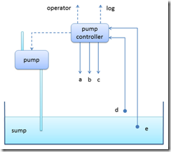
To bring yourself up to speed regarding the problem scenario, please quickly head over to Carlos article. As a teaser just let me show you his diagram to describe the overall situation where a small program is supposed to help:
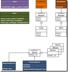
After briefly presenting the problem, Carlo jumps right into drawing class diagrams. Here´s his final solution:
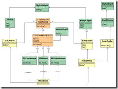
Unfortunately I can´t glean from it, how his solution is supposed to function ;-) His presentation of the solution is just a static diagram, i.e. a depiction of some structure. However, software mainly is a dynamic beast. It´s supposed to do work, to process data.
This is, why I prefer to do software design differently. So let me explain how I´d tackle the problem.
Abstract problem depiction
I think it´s prudent to speculate about programming language artifacts as late as possible. Wielding classes is programming, is rolling in the dirt of the concrete. Designing, on the other hand is approaching a problem first on a higher level, leaving out details – in order to move forward more quickly and to not fall into the trap of premature optimization.
Yes, in the end all lofty design needs to be attached to nitty-gritty code. But why limit ourselves in such a way right from the start?
Also just a drawing, Carlo´s problem depiction is very concrete. I find it hard to jump to any conclusion from that, like which classes there should be. So I like to first draw the system to design (STD) in a more abstract manner. Here´s my system-environment diagram for the sump problem domain:
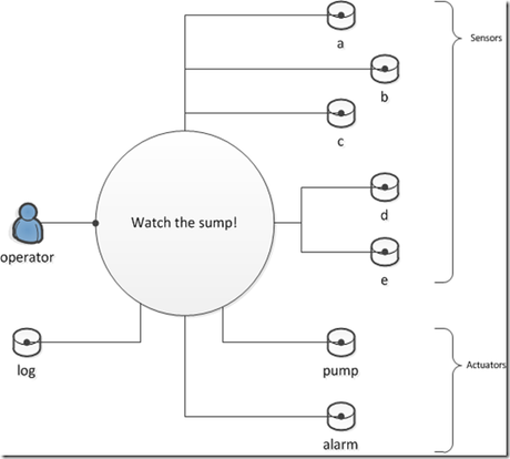
As you can see, I introduced a user role: the operator. Carlo did not talk about it, but I think it´s necessary to have at least one user in the picture. Otherwise it´s not clear why there is a STD at all. Someone has to benefit from it, need it for some purpose. Maybe there should be even more users, like the personnel of a plant who depend on the alarm to sound? But I leave them to the imagination of the reader, to not overcrowd the picture ;-)
The operator is not the only relevant “entity” in the environment of the system. There are sensors and actuators the system has to deal with. I call them resources. Whereas a user role depends on the STD, the STD depends on resources. That´s why the lollypop line ending points away from the STD.
Wrapping the environment
Once I identified the basic dependency relationships, I like to remind me that each should be encapsulated in some way. The innards of the STD should not depend directly on the environment, or to be more precise: on infrastructure APIs to communicate with the environment. This would make the system hard to test.
So I put small symbols in my drawing representing user roles and resources as mere aspects of the solution. Aspect to me means “a set of properties that can change independently of others”.
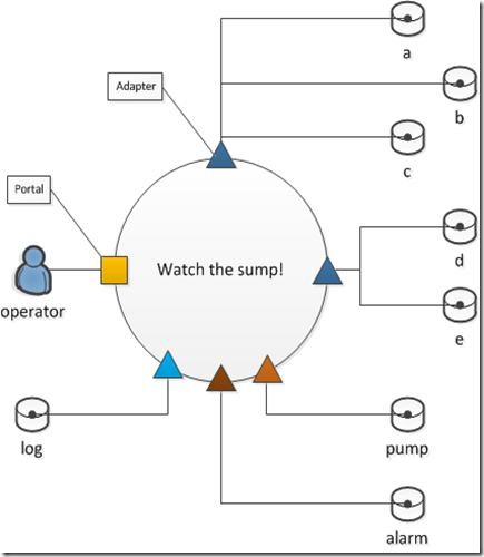
And even though you might not be able to imagine the API of the pump might ever change… there is at least one other kind of pump other than the real pump I want the system to be able to communicate with: a mock-up pump.
When testing the most important parts of the STD, I don´t want to be forced to always connect them to a real pump or any other user role/resource. So there needs to be a way to replace any environmental “entity” with a mock-up. This can be readily accomplished by encapsulating all environmental dependencies in some way.
The rectangles and triangles show me, what I need to do: define an interface for each user role/resource, which then can be implemented by a real API wrapper as well as a mock-up. (If you like to use an abstract class instead, you´re welcome to do so.)
Here are the interfaces for sensors a to e as well as for the pump and the alarm:
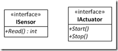
Yes, I think only two interfaces are required. All actuators behave the same: the pump needs to be started and stopped, the alarm needs to be started and stopped. And all sensors deliver their current value when asked. That´s the simplest wrapping I can come up with. And that´s an important point for me here: environmental entities should be wrapped as thinly as possible. This is to make it most easy to implement mock-ups and also to make testing usage of the environment APIs as easy as possible.
Carlo differentiates between digital and analog sensors – which nevertheless look the same on the interface level – and then further refines them into gas level sensors and level sensors. I would not have done so – at least not at this point, I guess –, but it´s ok with me. What´s important is that these refinements use composition over inheritance:
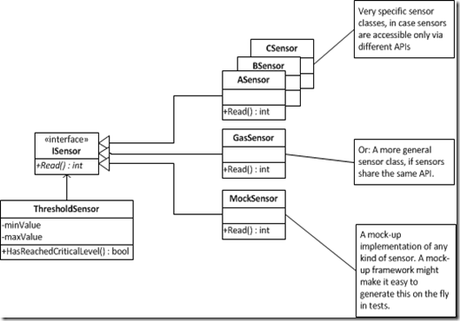
Each threshold sensor instance has its own ISensor instance assigned to it – probably by injection upon construction. It´s configured with an appropriate min/max value and the wrapper around the physical sensor:
var a_sensor = new ThresholdSensor(…, new ASensor());
Other than Carlo my classes would be more concrete the closer they are to the iron: I´d go for a ASensor, BSensor etc. classes implementing the simplest interface (ISensor). That way the least mount of code would be in there, i.e. testing would be as simple as can be.
Carlo on the other hand differentiates on a pretty high level of abstraction: a COSensor is a ThresholdGasSensor is a GasSensor [1]. I don´t get, why I should do that – at least not in light of the given requirements. They tell me, there are different sensors. That´s obvious even from Carlo´s first diagram. So what I can speculate about is, whether those different sensors are talked to using the same or different APIs. From that I would derive whether to implement the ISensor interface in a more general manner (e.g. GasSensor) or very specifically for each sensor type (e.g. ASensor etc.).
Beyond that, though, I don’t see there is a difference between sensors. Even the ThresholdSensor class is a convenience class ;-) It makes the common sensor interaction more specific, it introduces a sensor abstraction to gloss over differences. So I´d say, on this level of abstraction all the different sensors are the same. That´s the whole purpose of this class. One logic to rule all specific sensor API wrappers of a certain kind.
Architectural assumptions
Architecture to me is design with regard to non-functional requirements. After getting a view from 30,000 ft on the problem with the system-environment diagram, some thoughts on architecture might be in order. So what are non-functional requirements of Carlo´s sump scenario? And how do they influence structuring the system?
Well, as it seems, nothing much relevant to architecture is imparted by the requirements description. Performance, scalability, usability, security, robustness… no information on these and many other aspects. No details on the sensors or pump or alarm.
So I´m making two aspects up to become a bit more concrete. This is necessary to actually move forward. System structure is a solution to a concrete problem. That means, as long as the problem is not very concrete there is not really a right or wrong structure. Anything goes.
The assumptions I´m going to make are:
- The STD is supposed to run as a service on some computer attached to the sensors. Once the computer is switched on the STD will start doing its work. It will monitor the sump, start/stop the pump as necessary, and issue an alarm in an emergency situation.
- Polling the sensors periodically is enough to deal with changes in gas concentrations and water level. Whether that is every 100 msec or every 60 sec is not that important, I think – as long as processing the data does not take longer than the polling interval.
- Sensor and actuator APIs can actually be wrapped as to conform to the resource interfaces described above. I explicitly neglect any configuration or startup/shutdown ceremony.
- Actuators are wrapped in an idempotent way: switching on a pump that´s already running does not make a difference.
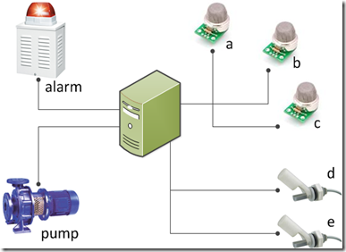
This is how I imagine the setup:
Modeling the solution
Now for the fun part. How should the whole system work? Carlo´s talking about this, but when I look at his blog article I don´t see it. The result of all his work is, well, just a structural diagram. All explanations about functionality are lost.
I deem it no virtue to be able to “reverse engineer” a class diagram to get an idea how things are working. If that´s all you have, a class diagram, well, then you have to do it. But my approach to software design and programming is, to avoid this kind of extra work. Develop software so it can be understood and changed easily. That requires to make functionality, i.e. how things play together, a first class citizen of the design.
This is, why I view software as a set of interactions with its environment. Yes, I´m modelling functionality using interactions or behaviors, not objects. At least objects as “bags of behaviors” are not where I start. My reason is simple: it´s notoriously hard to find such objects in the requirements. Except… yes, except for requirements dealing with real world things. In so far I´d say Carlo´s cheated a bit ;-) when he chose his scenario to demonstrate his object-oriented approach. The scenario makes is particularly easy to arrive at a class decomposition of the problem. For many, many developers, though, it´s not that easy because they deal with totally different stuff.
However, required behavior is always present. Software as a whole is always supposed to do something. So why not start from there? Start with one “thing” a software should upon request from a user role. Whatever has to be done thus is always triggered by some event in the environment. For the sample scenario that´s trivial: the operator starts the sump monitoring service by switching on the computer.
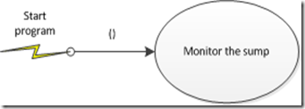
About this picture I can talk with the customer or a user. It´s dead simple. I can ask them, if that´s all to the interaction “Start program” – on this level of abstraction. The program is started with no further information. From then on it just runs…
If everyone agrees I can drill down. What does “Monitor the sump” mean?
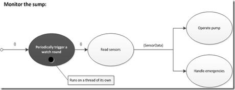
It means, this should be done periodically done. That´s a non-functional requirement. So it should show up in my model somewhere.
What has to be done periodically? Reading the sensors aka polling – and then acting on the data read from the sensors. That means the pump has to be switched on/off as necessary. And in case of an emergency the alarm has to be switched on.
I guess I could talk with a user on this level of abstraction, too. He could tell me, if I understood the problem domain correctly. And if´d be interested we could drill down further:
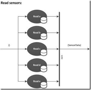
Reading the sensors could be done in parallel. They are independent of each other. And once all the readings are in, they can be packed up in a SensorData structure for consumption by the “domain logic”.
Note the drums next to the process steps. They signify a dependency. The process step depends on a resource, it accesses the resource in some way.
Ah, by the way: did you notice how I “stepped into” process steps. The previous diagram refines the process step “Read sensors” of the diagram above it. And that diagram refines the process step “Monitor the sump” of one diagram before. So what I´m doing here is truly modeling on different levels of abstractions.
No, I´m not using the L-word here. I don´t care much about layers. I never draw a layer diagram to start a software design. It simply does not help me in any way. It´s either trivial to state which layers there are – or limits my freedom in designing a solution.
Now comes the interesting part. How does the monitoring software actually do anything with the sensor data?
There are two “things” in the environment to control: the pump and the alarm.
The pump has to be switched on/off depending on the water level. However, if the methane sensor signals a certain value, the pump needs to be switched off regardless of the water level[2]. Both situations are assessed separately. The combined result then is evaluated to finally decide whether the pump needs to be switched on/off [3].
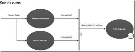
Whereas the “Read *” process steps do not add anything to the basic interface methods of the sensors, “Switch pump” contains some logic on top of calling the pump interface. But that does not hurt. The functional unit for “Switch pumpt” is easy to test due to IoC. It just knows an actuator interface and thus can be made to work on a mock-up during testing.
And now for the final refinement:

Straightforward, isn´t it? Assessing the gas readings is pure “domain logic”. Does is matter it also gets water level sensor data? No, I don´t think so. That´s trivial excess information. To separate sensor data to deliver it in a more fine grained manner, would not add much at this point. It´s an optimization, if need be.
Abstracting classes from the model
The modeling diagrams show how the solution is going to work. I´d say they can be understood pretty much even by a user, not to speak of a developer. To me they make clear where and when certain decisions are made. And they do so on many levels of abstraction, so I can explain/learn about the system at my pace/according to my needs. No reverse-engineering, no code archaeology necessary.
And the best part is: what you see above is the code to be executed. Almost. And of course on just a high level of abstraction. But nevertheless it´s code.
But how can such bubbles be executed? Well, I´m gonna show that in a future post, I guess :-) For now I´d like to focus on just what Carlo has provided: the model.
To live up to that, though, I need to do one more step. I need to show you the classes my design approach leads to.
Please note: For me classes don´t stand a the beginning of the design process. Rather they are the closing bracket matching the opening bracket of the system-environment diagram. Some classes might be easily gleaned from the requirements. Well, if that´s the case, write them down. Great – but be careful. They´re still lacking justification, until you assigned them functionality. (With the exception of pure data classes.)
That´s why I leave classes out as long as possible. They are abstractions, they are grouping constructs. They bundle “stuff” that belongs closes together than other stuff. So why should I start think about classes before I know what my “stuff” is?
The “stuff” of software is functionality. Or in more technical terms it´s functions, procedures, that means methods. That´s why I start by compiling the methods I need to deliver certain functionality. I do that top-down. And I do it in a cross-cutting way.
So what I´ve presented you so far is an assembly of methods. Each ellipsis can be translated into a method, sometimes a function, sometimes a procedure.
But here´s the trick: only leafs of the tree the above diagrams are spanning need to become methods; the are the actual operations of the software system. Any darkly colored ellipsis stands for such a leaf. The intermediate nodes of the flow network need not be encoded in any 3GL programming language. Their sole purpose is integration.
Here´s an overview of the whole model with operations colored according to class:
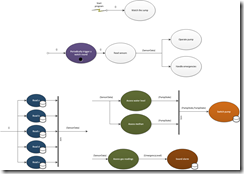
As you can see, I cam up with six different classes as work horses for the software system. That is, four of them are in addition to the basic wrapper classes for resources.
Now let me direct your attention to what´s missing: dependencies.
See how the classes each stand pretty much on their own? In Carlo´s class diagram there are so many lines of different kinds going in all directions. Some signify abstractions, some composition. It´s – sorry to say, Carlo – a bowl of spaghetti.
I dare to say that on the other hand the classes I came up with are not less focused in their responsibilities – but less entangled and thus much easier to understand. And there is no controller class either – which was the whole purpose of Carlo´s exercise ;-) Each method in the classes will be small, i.e. easy to test, easy to understand.
The classes are so little connected, I hardly need a class diagram at all. Why should it tell me anyway except for, well, the structure of data? But since the problem scenario hasn´t to do much with data, there is no need for a class diagram. I´m perfectly fine with the above data flow diagram annotated maybe with class names to make it a bit easier to find the methods in the code base.
Inevitable extensions
Two extensions I´ll leave open for now. This article has already gotten quite long.
- Logging
- Pump failure detection
I´d say, as long as it´s easy to add these requirements later on, my design could be considered at least reasonable. We´ll see…
Critique
One argument I can foresee: “What you do, Ralf, is just functional decomposition like in the 1970s. And we know that´s not gonna work.”
Well, yes, that´s a kind of functional decomposition. And I don´t see what´s wrong with that. Since software is about actions, process, behavior, “functions” are what we should be looking for. That´s the very stuff, software is build out of.
That said, I´m not opposed to object-oriented concepts and languages features. Right to the contrary. That´s all nice and well – where it´s appropriate.
As you can see I make use of interfaces. And I like to encapsulate data. And of course what belongs together should go together into a class. Or a component. Or an assembly. Or a process.
But I´m not on the outlook for small virtual machines. Encapsulation of details (state, logic) is great. But it´s an optimization. Trying to start software design with classes thus to me more or less is premature optimization.
If you´re serious about the term “class” then don´t just understand it as a schema. Also view it as an abstraction of functionality, i.e. a name for a group of methods. And like any other class of stuff software classes then are the result of collecting stuff first. Then classifying it. That´s what Linné did. That´s what we as software designers should do.
Some classes might be obvious. But more classes are not, I´d say. They need to be abstracted from functionality. That´s what I´m doing. But because of this approach I´m not doing plain procedural programming.
There´s also another telling trait of my approach: data flow. Procedural programming never used data flows. Flow-charts or structograms relied on global data, not data flowing from step to step. But that´s what I favor. It keeps dependencies local. And it makes it more obvious what´s happening.
Summary
So much for my plea for Flow-Design :-)
This was fun. I finally was able to contrast my approach with a “true” OO approach. The result is looking different in many regards – but at the core there is some overlap. Of course. Carlo and I agree on the need to wrap resources behind interfaces.
However, we view the software world structured differently. He starts with a vision of small virtual machines (objects) whereas I view software as a bunch of processes (integration) made up of smaller and smaller steps (operations).
Now it´s your turn to compare and assess the two approaches. Looking forward to some discussion – if you like.
Footnotes
[1] I´m aware Carlo also ponders the possibility to have just three instances of ThresholdGasSensor. But he seems to favor more specific classes. That´s at least what he chose to depict and thus make his final solution more complicate.
[2] To me it seems Carlo´s design not really caters to this requirement. For him a gas sensor signals either a critical state or not. I have followed him in this so far. But if I think more closely about it, the critical level for an alarm and for switching off the pump might be different. The GasSensor interface might be too limited. But the requirements are not precise on this. So I´ll leave it at that.


